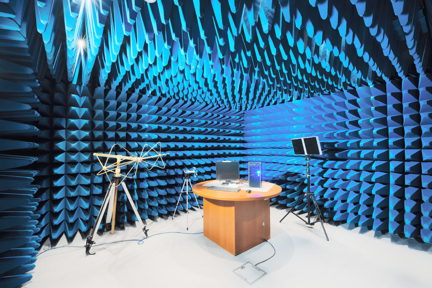
We were given a task of developing a low-level filter driver for the Display Port interface to address the issue of changing DisplayPort Configuration Data (DPCD) under Windows 10, specifically for DisplayPort 1.2. Not an usual custom linux software development task, isn't it? Additionally, we were to create a program to interact with the driver. For testing, we were provided with a Philips 242E1GAJ monitor and an MSI PRO DP21 11MA-210RU computer.
At first, the kernel development went well; we resolved issues related to registering the driver in the system, incorporating it into the monitor driver stack, and managing data transmission to and from an external program. However, challenges arose when we began testing the interaction with the DPCD itself. Despite following official documentation and utilizing the special DXGKDDI_DPAUXIOTRANSMISSION function, we were unable to extract any data from the DPCD, regardless of the parameters used.
Through a detailed study of WDDM files, we discovered that this function, along with many other DisplayPort functions, lacked implementation and served merely as a template for custom driver creation. Given the lack of time allocated for such an extensive task, we decided to switch the operating system to a Linux-based alternative thus offering our linux development services. We experimented with Debian 9, 10, and 11, but none of these versions successfully managed DisplayPort functionality 'out of the box' to transmit the image onto the monitor. Eventually, we transitioned to Ubuntu 22.04.1, which immediately established a working connection with the monitor via DisplayPort. This will be elaborated on further.
It's important to note that in Linux, there is no equivalent to a filter driver, nor are there layered drivers. However, Linux allows for the interception and manipulation of a driver's function calls. Essentially, we can redirect the call from the original function to our custom function. But this was not necessary for our current task. To develop a driver for Linux, you must install header files compatible with your kernel version.
sudo apt-get install linux-headers-$(uname -r)
In cases where the Linux kernel is compiled from source code, the linux-headers for your kernel version may not be available in the repository. However, this is not an issue as they are generated during the kernel compilation process.
Let's begin with driver creation. Direct interaction between an external program and a driver is not possible. Instead, a character device is created, to which a program can connect and execute data transfer calls to the driver. There are four available modes: read, write, simultaneous read and write, and no parameters. The device should be created at the time of driver registration and deleted alongside it. It's important to remember to delete not only the device itself but also the device class when deregistering the driver.
int register_chrdev(unsigned int major, const char *name, const struct file_operations *fops);
We encountered problems when creating the file_operations structure. The challenge involved defining a function to handle calls to the ioctl (Input/Output Control) device. In Linux kernel versions up to 3.x, defining the handler function was accomplished by setting the .ioctl parameter.
In more recent kernel versions, this parameter is no longer accessible and has been replaced by unlocked_ioctl for several reasons related to new architectural changes. More information on this can be found in discussions on the Big Kernel Lock.
static struct file_operations fops =
{
    .unlocked_ioctl = etx_ioctl
};
Much of the documentation on developing drivers for Linux is based on older kernel versions, making it challenging to find information relevant to current versions. However, documentation for the current kernel version can be accessed here.
In the current kernel versions, all ioctl-calls are directed to the function assigned to unlocked_ioctl. The function, including its parameters, is defined as follows:
long etx_ioctl(struct file *file, unsigned int ioctl_num, unsigned long ioctl_param);
Our primary focus lies on the last two parameters: ioctl_num and ioctl_param. As the name suggests, ioctl_num is the command number, which must be predefined.
#define "ioctl name" __IOX("magic number", "command number", "argument type")
Where IOX should be:
IO – without parameters;IOW– for writing parameters (copy_from_user);IOR – for reading parameters (copy_to_user);IOWR – for reading and writing parameters.
In the case of DPCD, we assumed that read and write commands would suffice. We will delve into more details later. Essentially, you need to know the address and the data that can be written. However, some DPCD fields span more than one address; this means that integral data must be logically divided across multiple addresses. If you aim to change any available field from the application, it is preferable to use the basic approach of specifying the address and data in separate commands. Consequently, a specific command was assigned to each field.
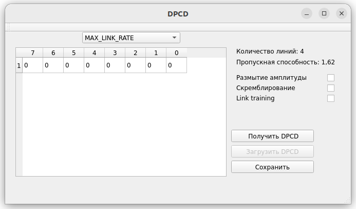
Now, let's delve into understanding DPCD. What exactly is it? As per the documentation, DPCD is an address space in the DisplayPort device that provides data for setting up and initializing channels. The documentation specifies which address corresponds to which parameter, so we will not elaborate on that here. Crucially, each address value consists of 8 bits. Notably, not every field consists of a single address. There is a function drm_dp_dpcd_readb for working with DPCD fields, which becomes available with linux-headers. Its prototype is in drm_dp_helper.h.
ssize_t drm_dp_dpcd_readb(struct drm_dp_aux *aux, unsigned int offset, u8 *valuep)
You might wonder how to obtain drm_dp_aux. Currently, there are no direct means to do so. However, the monitor functions and the video driver creates and utilizes it in some way. It's important to note that our PC uses an integrated Intel video card. If you're using an AMD or Nvidia video card, your approach may differ.
The Intel i915 driver is included with the Linux kernel. Given that the source code is open, why not retrieve the necessary parameter from there? We downloaded the kernel source code and navigated to drivers\gpu\drm\i915\display\intel_dp_aux.c. Then, we added the necessary functions to it.
static struct drm_dp_aux *static_dp_aux_ptr;

struct drm_dp_aux *intel_dp_aux_get_struct(void) {
    if (static_dp_aux_ptr == NULL)
        printk(KERN_INFO "Backlight: Could not init the aux_ptr!\n");
    return static_dp_aux_ptr;
}

EXPORT_SYMBOL(intel_dp_aux_get_struct);

static void intel_dp_aux_set_struct(struct drm_dp_aux *dp_aux) {
    static_dp_aux_ptr = dp_aux;
}
At the end of the function void intel_dp_aux_init(struct intel_dp *intel_dp), we add a call to our new function:
intel_dp_aux_set_struct(&intel_dp->aux);
So, what have we achieved? We have created a pointer to the structure necessary for reading DPCD, developed functions for writing and reading this structure, exported the reading function for use in other drivers (using EXPORT_SYMBOL), and added a function call for writing the structure into the initialization function. Then, we compile and install the kernel; through calling the function intel_dp_aux_get_struct, we obtain the structure. Don't forget to specify external in the function prototype.
Further tasks are trivial and will not be discussed here. Where necessary, you can read the data received in the ioctl function via copy_from_user and return the data on request via copy_to_user.


 2002–2026