


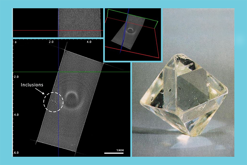
Our developers were given a task to create software for a microtomography device, which they successfully completed and proceeded to stuff the tomograph with sunflower seeds, bolts, capacitors and moths. The device's professional uses extend more to things such as examining diamonds and avoiding buying holed ones.
16th of December is the birthday of Johann Radon, Austrian mathematician and rector of the University of Vienna, who in 1917 introduced an integral transform of a function with multiple variables, which is closely related to the Fourier transform and now used in all tomography devices.
Johann Radon was a professor in six universities (in one of them even without a chair) and the president of the Austrian Mathematical Society. In Austria there is an Institute for Computational and Applied Mathematics, and a medal named after him at the Austrian Academy of Sciences. Read more about the process of tomography software development and the problems tackled below.
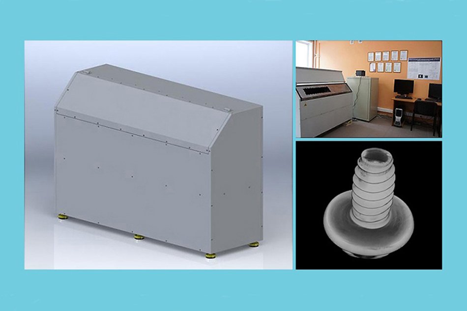
Microtomography device
Scientists created a microtomography device. It provides information about the inner structure of various materials to a degree of accuracy of one micron. It can be useful in examining diamonds, for instance.


X-Ray emitter
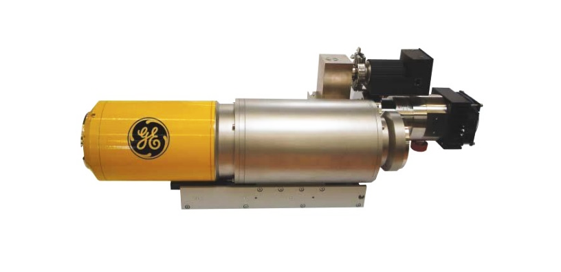
- Voltage: 20–160 kV
- Amperage: 0–250 µA
- Wattage: 10W
- Focal spot diameter: 1–5 µm
X-Ray detector based on a CCD-matrix
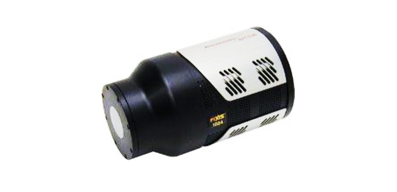
- CCD sensitive area dimensions: 2048 x 2048 pixels
- Geometrical size of a pixel: 13 x 13 µm
- Geometrical size of CCD sensitive area: 27.6 x 27.6 mm
- Inbuilt two-speed A/D converter (16-bit 100 kHz & 16-bit 2 MHz)
Positioning system
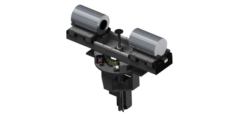
Rotor travel:
- SEMM (segment electromechatronic movement module) – 360°
- LEMM (linear electromechatronic movement module) – 100 mm
Positioning precision, not less than: ±0.5 µm.
Rotor travel speed: from 0.01 up to 20 mm/sec.
Wattage (at an input voltage of 70V): 0.7 kW.
General technical specifications of the device
| № | Name of specification | Required value | ||
| 1 | Number of resolving elements in detector, µm | 2048 x 2048 cells provided that the size of one element be not more than 13.3 x 13.3 | ||
| 2 | Resolution | 13 µm | ||
| 3 | Mass and size characteristics, mm/kg | 504 x 992.5 x 1504 450 |
||
| 4 | Field of vision, mm | 1 | ||
| 5 | Working range of wavelengths, Å | 0.3–2.3 | ||
| 6 | Positioning precision of electromechatronic movement modules in the positioning system of x-ray microtomography device, µm | ±1 | ||
| 7 | Safety standard | GOST 12.1.030-81 | ||
| 8 | X-ray protection, µSv/h | 1–3 |
Microtomography device software

Mathematical algorithms used:
- Inverse Radon transform
- Marching cubes
- Gaussian filter
- Filtering/convolution, projection normalization
Implementation and technologies:
- C++/Qt
- Ubuntu, Windows
- CUDA
- Volume voxel rendering of a model
- Custom format for storing images with 12-bit grayscale
- Client-server reconstruction architecture
- Saving volumetric data in the form of octrees
Work effort: 5233 man-hours.
Debugging was conducted on raw data (projection snapshots) received from the tomography device.
Algorithms
First of all it was necessary to select mathematical tools to solve the problem. The primary algorithm – the inverse Radon transform – was included in the task definition,

but it had to be adapted to the specifics of our task and supplemented by a couple of additional supporting algorithms. For instance, since the object was x-rayed by a single ‘lamp’, it was necessary to adapt the formulas of the inverse Radon transform for conical, not frontal projections. The standard algorithm presupposes that an object is x-rayed by a beam of parallel Rontgen rays coming from an infinitely-distant source. In reality the source of rays is point-like, explaining why the beam has the form of a cone. Considering this, it was necessary to introduce into the algorithm a transform of coordinates from a conical system into an orthogonal one.
The first stage of calculations involves preliminary filtering/convolution, and normalization of projections. This is necessary for the reduction of noise and highlighting densities on the projections.
The ‘marching cubes’ algorithm was used to create 3D models of object surfaces in a standard format to be viewed in 3D editors such as Kompas 3D, SolidWorks, and 3DS Max. The essence of the algorithm is found in the following. It is directed through a scalar field, taking eight neighbouring position readings at a time (thus forming an imaginary cube), then determining the polygon(s) needed to represent the part of the isosurface that passes through this cube. The individual polygons are then fused into the desired surface.

In this project, the Gaussian filter refers to a matrix filter for image processing which uses a convolution matrix. A convolution matrix is a matrix which is ‘multiplied’ by the value of the image pixels to obtain the desired result. The filter is used for smoothing voxel data and slice projections which, in its turn, helps to enhance the quality of the 3D models generated.
Implementation and technologies
Over the course of our work we have also created a number of tailored technical solutions: a library for volume voxel model rendering; technology for video recording while manipulating a model; a custom format for storing images with a 12-bit grayscale; a method for saving volumetric data as in ‘octrees’; and algorithms for polygonal 3D modelling.

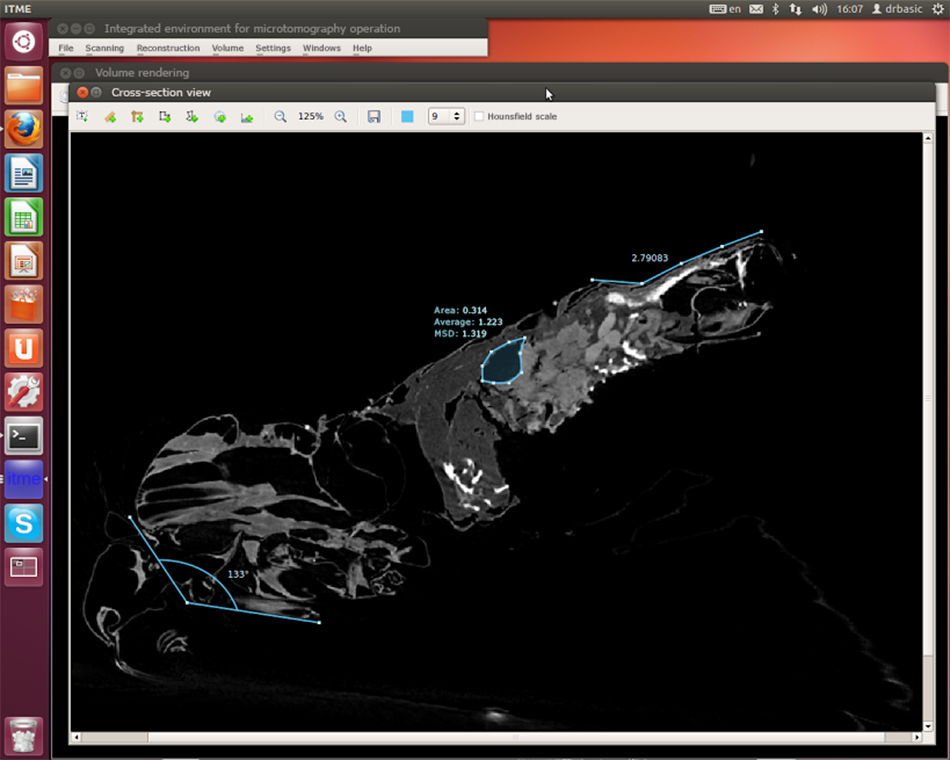
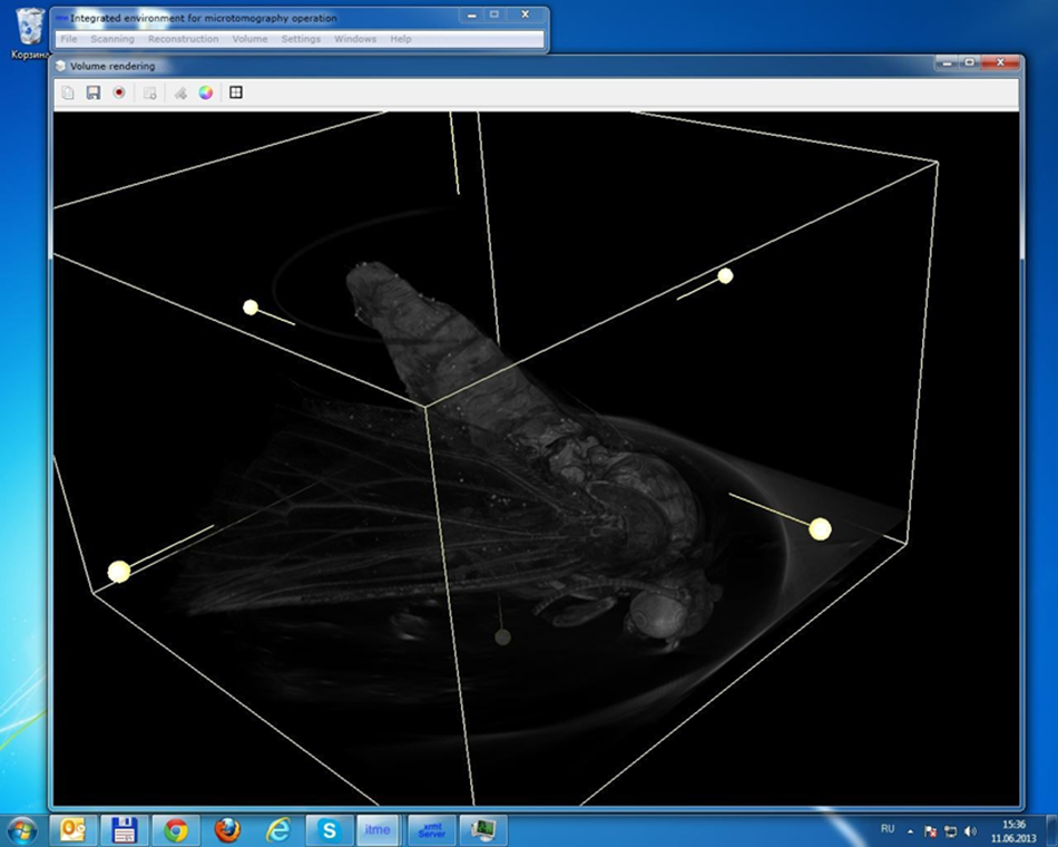
Volume voxel model rendering was used in the project to provide the possibility of viewing the model with the option of rotation and scaling in real time. A voxel is a 3D pixel. With the help of voxel rendering an operator also acquiring useful tools for defining a display area with an automatic increase in the level of detail, and the possibility of placing the cutting plane at any angle, all in the space of two clicks. Through manipulation of the cutting plane one can then obtain an image of the cross section with the maximum resolution.
An octree (a tree of octants) is a tree data structure in which each internal mode has exactly eight children. Octrees are most often used to partition a three-dimensional space by recursively subdividing it into eight octants. In this project, an octree helps to display the data in a preview mode, in which the data invisible to the user is redundant. Thus, for example, volumetric rendering receives a set of data for display with the level of detail depending on the chosen area with the help of an octree, which ensures high FPS when the whole model is in view and at the same time increased level of detail if a smaller part of the model is chosen.

Debugging
The next stage was optimization. The tomography device produces a 360-degree shot for one object, each of them with the resolution of 8000 x 8000. Since the amount of data processed is so great, it would have been inefficient to solve the problem with a brute force approach. Even though this fact had been taken into consideration as early as the design stage, we still had to optimize and adapt algorithms several times starting with the first incarnation. It was required that the time taken to create a 3D model of a microstructure wouldn't exceed two hours, which is why the optimization stage had been initially planned as part of the project. In the process of testing the first version we realised that using standard formats for storing image projections was not suitable for the project. Input data contains images in TIFF format with a 16-bit grayscale. Such depth of colour is redundant for calculations, besides it requires a great amount of drive space, network channels, RAM and processing time. On the other hand, the standard 8-bit grayscale seemed insufficient for retaining the precision of reconstruction. For that purpose, a special format for storing images with 12-bit grayscale was developed.
The horizontal scaling of calculations was built into the technical project. The 3D model reconstruction, which is the main computational task, was divided into small package tasks which were distributed by the central software module among the servers in a cluster. The servers used CUDA technology which allowed for the employment of the computational capacities of graphic processors for calculations. The time required for calculating one model was reduced proportionally in accordance with the number of servers in a cluster, as the computational tasks were perfectly parallelized and all servers were operating at 100% load.
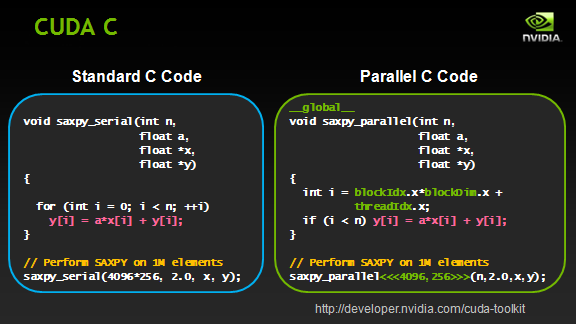
CUDA architecture is used not only for high-performance graphic calculations but also for various scientific calculations with the use of NVIDIA video cards. Scientists and researchers use CUDA widely, in various spheres including astrophysics, computational biology and chemistry, modelling of the dynamics of liquids, electromagnetic interactions, computer tomography, seismic analysis and many others. CUDA provides the possibility of connecting to applications which use OpenGL and Direct3D. CUDA is cross-platform software for such operating systems as Linux, Mac OS X and Windows.
In our project we use CUDA for the main process – the reconstruction of 3D data from projections. In view of the fact that graphic processors have a specialised set of commands, reconstruction calculations fit well with the graphics cards using CUDA technology. Working on CPU this task takes longer to complete both at the stage of design and execution.
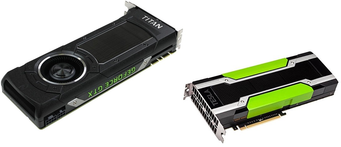
Our software supports the following cards:
The task presupposed that the software should operate on Microsoft Windows XP/Vista/7, or Linux. Hence, the cross-platform character of the solution was a key part of the project from the beginning. C++/Qt was chosen as the programming language which allowed for a single source code, and building software for various operating systems.
Videos


 2002–2026